Experimental Incubator/ei prototype designing
Jump to navigation
Jump to search
3.0 "Fermento" - Current prototype of experimental incubator
This third generation is different from the previous second generation (v2.1, code name "Mamut") design in a number of important ways.
Differences
- It has a full 6 button layout, back, enter and a star-shaped cursor-pad
- The keypad is made 'detachable' from the rest of the PCB, allowing connection via 3 wires (GND, VCC, A0)
- It uses i2c for controlling the LCD instead of using up a lot of digital pins; connected via 4 dupont wires (GND, VCC, SDA, SCL)
- It uses an Arduino Pro MINI (328 @ 16mhz) board which cost only 3 euro/pc
- All the pins of the arduino are broken out on extra pin-headers for driving outputs or connecting extra inputs.
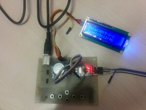
The photo to the right shows the first (0) version.
From left to right, you can see
- USB-connector for power (only)
- Two 3 pin headers for connecting 1-wire tempsensors (ds18x20's)
- The six holes there are for mounting screw-terminals to connect the sensors instead of pin-headers)
- The ds1307RTC. It provides a realtime-clock and some eeprom storage for settings/etc.
- The arduino Pro Mini, soldered to the PCB via pinheaders.
- The loop of dupont-wire is for connecting the i2c pins to the board. These are not in the 'standard' pinout of the arduino pro mini. Different designs have them on different positions. This solution seemed the most useful.
- Above and below the Arduino Pro Mini are two rows of pins; 24 holes per side. These are for mounting double-row pin-headers to break out all the pins available on the Arduino Pro Mini for connecting actuators, SSR's, etc OR to extend the design with more/other sensors.
- A six-button keyboard is shown at the bottom of the board. The PCB has been carefully designed to allow cutting the PCB into two sections, seperating the key-pad from the rest of the PCB and allowing it to be connected using a dupont female-female wire (3 connections). Footprints for the required pin-headers are already present. On the photo the holes for these have not been drilled, however.
- USB-connector: $0.20
- RTC-module : $1
- Arduino Pro Mini: $2
- Pin-headers (single): $0.20
- Three-pin screw-terminals: $0.60
- Buttons: $1
- Double pin-headers: $0.40
- Dupont-wire: $1
- LCD+ I2C module: $4
- Temperature-sensors: $6
$16,4
The third generation is going to be PCB based with fallowing components and sensor attachements suggested.
| Component | Function | Model Specifications | Amount | Cost (€) | Purchase links | Component Suggested by |
|---|---|---|---|---|---|---|
| Arduino Pro Mini (clone OK) | brain | 328 @ 16mhz | 1x | 3 | DealExtreme | Arnd |
| LCD Display+I2C module | display data | 16x2 via pcf8574A | 1x | 7 | DealExtreme | Arnd |
| Temperature sensors | to measure temp. | ??? | 2x | 8 | DealExtreme | Arnd |
| Solid state relay | switch on/off 220V elements | ??? | 2x | 6-10 | DealExtreme | Arnd |
| RTC (real-time-clock) module | keep count of time | DS1307 | 1x | 3 | DealExtreme | Arnd |
| Connectors for temp-probes | connect the temp-probes | ??? | 2x | 1 | DealExtreme | Arnd&Erwin |
| USB-connector | ||||||
| Pin-headers (single) | ||||||
| Buttons | ||||||
| Double pin-headers | ||||||
| Dupont-wire |
Total expected cost of all the items in THIS build is as follows:
This excludes cost for PCB (self-etched) or any actuators/ssrs/peltiers/etc.
For the info about Second Generation - Mamut please check here.
